This is a follow-up article from the previous article on the Linux PDA project. In this article I will
discuss the planning process for the device.
PineCube
Previously we asked two questions
regarding the possibility of using the PineCube hardware as a base for
a PDA device:
The current state of the PineCube project overall and ensuring they
are still in stock.
I’ve had some discussion on IRC and it appears some people are still
active there. There appears to be some active and ongoing work to build
a motion detection activated recording for the device. As long as the
hardware remains in stock, it should be possible to use this as a base
device. There appears to even be updated Linux kernels for the
device.
The current state of the LCD driver. Writing an LCD driver for the
Linux kernel from scratch is not something I’ve done before, so it will
be a lot of pain if I end up having to do that.
Apparently the display that is compatible is a
RB043H40T03A-IPS, that can be found here
for about $10 USD each (without shipping and GST). Apparently it is
designed for use with a 16 bit STM32 microcontroller.
As you can see in this video shared publicly via IRC, Gaimee has been able to get the
LCD working. Apparently:
<@gamiee> B[]
: it’s not touch. The source code from this preview is in PineCube
BSP
Some more investigation is required, after all Pine64
wiki says:
LCD touch screen panel information:
It must support touch right?
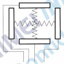
Touch Screen
Firstly I found out that for a similar
touch display, they use pins 37, 38, 39 and 40 for the touch
display:
LCD pins for touch
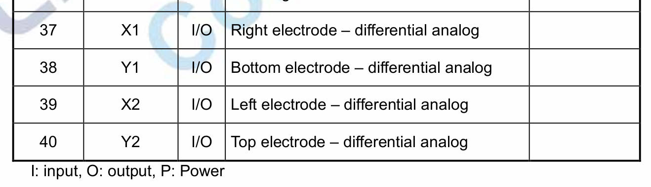
So far so good. I’m not entirely sure how this electrode setup works,
so I check further in the same document:
LCD electrodes
As you can see, we appear to be measuring the changing ‘resistance’
between two points on the display to measure each axis. This is
confirmed when we look further:
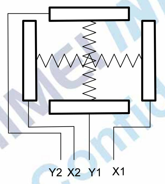
LCD linear response
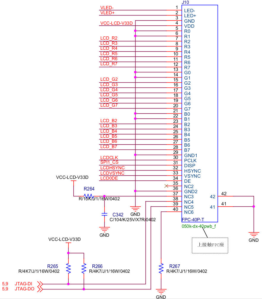
Awesome! So now we just need to look at the 40 pin connector on the
main board…
Weird, our pins are called NC, i.e. “No Connection” -
but they are clearly connected to something. We see that pin 37
is pulled up to 3.3V, a good start. We then see pin 40 pulled down to
ground, not so bad either.
Where things get weird is that pins 38 and 39 are attached to
JTAG-DI and JTAG-DO. Maybe they can read
analogue data and all will be good?
S3 ARM CPU
Reading the CPU
datasheet, on page 31 we see that PB12 and
PB13, the JTAG pins, are digital I/O only:
JTAG pin capability
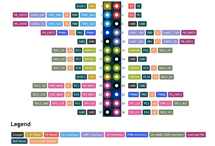
There is just one last hope… If PB12 and
PB13 are exposed externally, we could look to jump them
over to an ADC pin on the CPU!
PineCube GPIO pinout
Nope.
PineCube Conclusion
This hardware was already a challenge to work with. I was already not
happy with the form factor and the PCB stacking, but I was willing to
overlook it.
The real problem here is that the hardware would need a re-work in
order to get touchscreen capability working. Accessing PB12
and PB13 on a ball-mount CPU is going to be impossible, and
I really don’t want to solder the sort of pitch that 40 pin
connector will be.
This hardware will simply be too difficult to work with. We can
likely find something much more appropriate for the task.
Alternatives
So, it looks like we need a new base-board. There are a few
interesting options out there:
Raspberry
Pi – Interesting idea, but too powerful for a simple
PDA device. Very good hardware and documentation support. Many
touchscreen LCDs are supported and no LiPo battery support without some
additional help. The biggest issue though is that it partially
close-source with the Broadcom processor.
Beagle Board –
Again an interesting option, much closer to the expected specs and
capabilities. Specifically the BeagleBone Black
Wireless would be a proper option. The issue here though is finding
an affordable LCD display. There appears to only be one
offering at $50 for a small 4.3 inch display!
Seeeduino
Cloud – This is a cheaper alternative to the Arduino
Yun, a lightweight 64 MB Linux SBC with WiFi and backwards
compatibility for Arduino ATmega. This is a very interesting option, but
they appear to currently be out of stock (even on the Arduino store). It
does appear to now be retired in general.
Pocket
CHIP – Again, really close to what I am looking for. But.
NextThing.co went bankrupt and there is no point in developer
for a product that is already almost entirely depleted.
I’m literally not happy with any of the alternatives on offer.
Perhaps the lack of base-device hardware is what ultimately kills this
pipe dream?